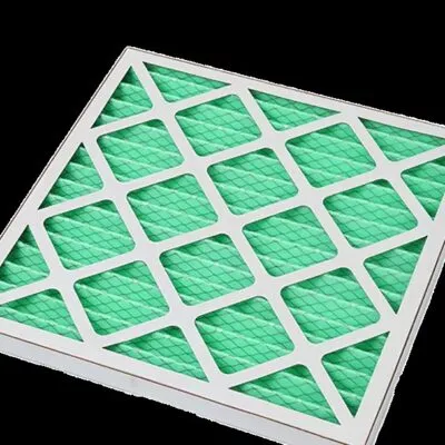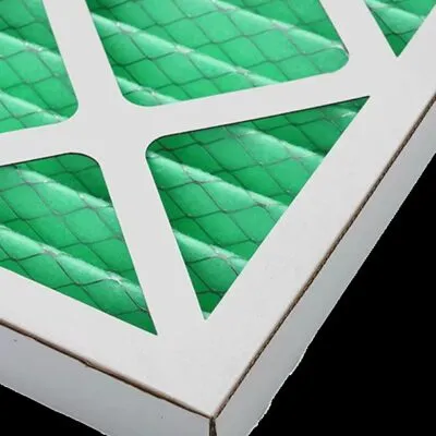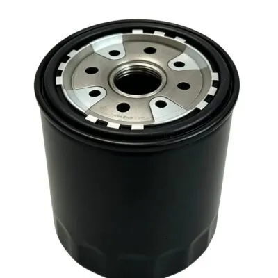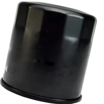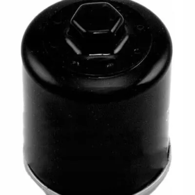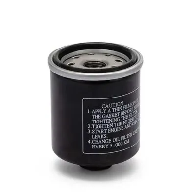
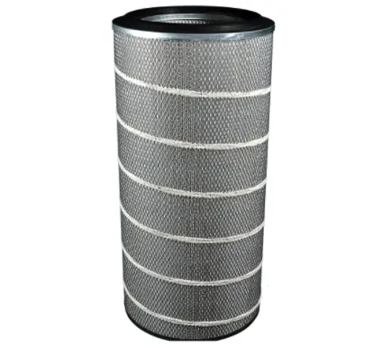
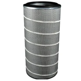
Air Intake Filter Elements for Gas Turbines
Product descriptions
Air Intake Filter Elements for Gas Turbines
1. General Information
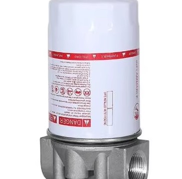
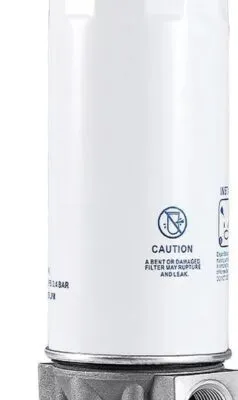
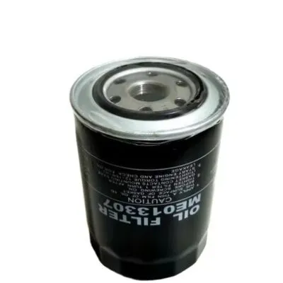
• Description: Air intake filter
• Type: TI 10-19SO 852908
• KKS: MBL19CP001
2. Dimensions & Physical Characteristics
• Height: 600 mm
• Outer Diameter: 328 mm
• Inner Diameter: 216 mm
• Sealing Diameter (Top): 250 mm
• Sealing Diameter (Bottom): 266 mm
• Filter Area per Element: 19 m²
• Number of Pleats: 320 ± 3%
• Filter Material: Ti10 special treated cellulose with 15% ± 5% PET fibers
• Construction:
• End caps, inner and outer supporting tube made of zinc-coated steel
• Polyurethane foamed gasket
3. Operating Conditions
• Maximum Operating Temperature:
• 60°C during normal operation
• 80°C peak (short time)
• Maximum Air Flow per Element:
• 1,250 m³/h for single element
• 2,500 m³/h for double element
• Maximum Filtration Velocity: 1.10 m/min
4. Filtration Efficiency (Test Dust – EN779-2002 F9)
• Coarse Efficiency: > 99.95%
• Fine Efficiency: > 99.64%
• Filter Class: F9 (EN779-2002)
5. Pressure Drop
Single Element
• Initial: 200 Pa
• Operational: approx. 800 Pa
• Recommended Maximum: approx. 1,500 Pa
• Recommended Maximum Dust Load: approx. 4–5 kg per element
Double Element
• Initial: 500 Pa
• Operational: approx. 1,100 Pa
• Recommended Maximum: approx. 1,800 Pa
Lifetime
• Guaranteed: 8,000 EOH or 10,000 cleaning cycles
• Storage: Under dry conditions
6. Detailed Construction Requirements (As Per Buyer’s Text)
A) Filter Media & Application Requirements
1. The media must comply with the original manufacturer’s specifications (MAHLE) regarding type of media and operating conditions.
2. The filter must have OEM-equivalent approvals from qualified authorities.
3. Number of pleats: 320 ± 3%
4. Total filtration surface: 19 m²
5. Proper pleat geometry and uniformity across total filter length.
6. Presence of an internal and external neck (Spacer) used for adjusting pleat spacing along the entire filter.
B) Internal & External Wire Mesh + Caps
1. Wire mesh (inner & outer):
• Material: ST14 hot-rolled steel sheet
• Minimum thickness: 0.8 ± 0.1 mm
• Galvanized coating thickness: 15 μ ± 1 μ
2. Material of top & bottom caps:
• ST14 hot-rolled steel sheet
• Minimum thickness: 0.8 ± 0.1 mm
• Galvanized coating thickness: 15 μ ± 1 μ
3. Mesh Specification:
• Expanded metal sheet ratio: 73% ± 3% open area
• Mesh size: mesh 12 for outer mesh + inner mesh
4. Punched wire sheet: Must protect the media from damage when in contact with sharp edges.
C) Polyurethane End-Cap Requirements
1. Polyurethane (Foam) material: Must be resistant to deformation during installation or pressure changes.
2. The polyurethane end caps must have strong and durable bonding, ensuring they do not detach during the filter’s operational life.
3. Filter Media Bonding:
• Must withstand minimum pulling force of 120 kg
• Must retain bonding strength at high humidity (up to RH 100%)
• Must maintain adhesive properties between –20°C and +60°C
• Adhesive must provide complete and permanent bonding of media to the caps
• Adhesive must withstand vibrations and shocks
Contact Us
Frequently bought together